Overview of Cardinality in Data Modeling
In data modeling, cardinality refers to the relationship of data in one database table with respect to another table. Two tables can be related as “one-to-one”, “one-to-many”, or “many-to-many”:
- 1:1. One row in table A relates to one row in table B. Using an entity-relationship (ER) model, 1:1 means that one occurrence of an entity relates to only one occurrence in another entity.
- 1:Many. One row in table A relates to many rows in table B. In ER modelling, 1:Many means that one occurrence in an entity relates to many occurrences in another entity.
- Many:Many (M:N). Many rows in table A relate to many rows in table B. In ER terms, many occurrences in one entity relate to many occurrences in another entity. For example, a student (table A) may sign up for many classes (table B), and a class may have several students in it. Many-to-many relationships normally require a cross-reference table, AB with two one-to-many relationships A:AB and B:AB.
A relationship may also be optional. Optional means that a row in one table doesn’t have to relate to any row in the other table. For example, not all associates are provided business credit cards. To put it a different way, an associate may have 0 (zero) or more credit cards issued by the company.
Data Cardinality in Centerprise
Centerprise supports the cardinality types listed above, and it expands on this concept by applying cardinality rules to any data source it supports, not just database sources. A data source is similar to an entity in the ER model, and may be a database table or view, flat or hierarchical file, or even email, ftp or web service data. A non-database source is most commonly a flat file, such as comma-separated values (csv) or Excel workbook. In a Centerprise dataflow, a flat file source acts similar to a single database table source. Centerprise also supports non-flat, or hierarchical sources, representing more complex data structures, such as trees containing a root node and a combination of descendant (child) nodes which may be parents to their old children nodes.
Centerprise implements 1:1 and 1:Many cardinality types in non-flat data sources by using tree layouts and assigning every node in the tree as a ‘Single Instance’ node, shown in the tree as , or ‘Collection’ node, shown in the tree as . The figure below shows an example of an object with a complex tree layout.
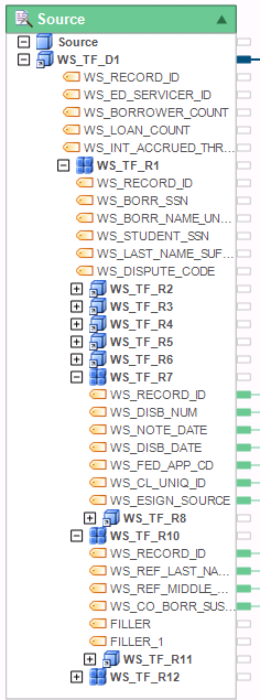
A single instance child node has a 1:1 cardinality (i.e. a 1:1 relationship) to its parent node.
A collection child node has a Many:1 cardinality to its parent node. In other words, each parent record may have 0 or more child records that are collectively referred to as a collection.
By mapping tree nodes in a particular way, as well as by using transformations, such as Sort, Join, Union, Flower, or Aggregate, to name a few, Centerprise allows you to effectively de-normalize required portions of tree data structures, and save that new representation of your data in a flat file or table.
Note: A reverse process to creating flat output is to join the denormalized or disparate data sources using TreeJoin transformation. TreeJoin transformations allow you to create data trees by joining multiple flat or hierarchical data sources.
Dealing with Data Cardinality while Transforming your Data in Centerprise
Understanding Centerprise Transformation Types and How They Impact Cardinality
With Centerprise dataflows, you can merge data from multiple disparate sources, split data from a single source into multiple destinations, and perform a series of relatively-simple to highly-complex transformations. Centerprise built-in transformations include field-level transformations such as expressions, lookups, and functions, as well as recordset-level transformations such as sort, join, union, merge, filter, route, normalize, denormalize, and many others.
Single vs. Set Transformations
Centerprise transformations are divided into two types—single (or record level) and set level.
Single transformations are used to create derived values by applying a lookup, function, or expression to fields from a single record. You can view results of single-record transformations as appending more values to the preceding layout. A name-parse function, for instance, takes a full name and breaks it into individual name components. These components can be mapped to succeeding transformations (including set transformations) or written to a destination.
Set transformations, on the other hand, operate on a group of records and may result in joining, reordering, elimination, or aggregation of records. Examples of set transformations include join, sort, route, distinct, etc. Data sources and destinations are also considered set transformations. Generally, set transformations operate on the entire data set. For instance, a sort transformation sorts the entire data set before passing along records to the next object. Similarly, aggregate transformations use the entire data set to construct aggregated records.
In Centerprise, the data flows between set transformations. Single (or record level) transformations are used to transform or augment individual fields during these data movements. The transformations in your flow need to be connected (aka mapped) in a certain way as to avoid cardinality issues while transforming your data. A cardinality issue in your dataflow will prevent it from running successfully, and will throw a cardinality error during flow verification or at run-time.
Avoiding Cardinality Issues while Designing your Dataflows
Keep the following rules in mind when designing your flows. They will help you avoid most common cardinality issues.
- A record level transformation can be connected to only one set transformation. For instance, a lookup or expression cannot receive input from two different set transformations.
- Other than transformations that enable combining multiple data sources—such as join, merge, and union—transformations can receive input from only one set transformation.
- Set transformations can receive input from any number of record level transformations as long as all these record level transformations receive input from the same set transformation. In other words, you can map any number of single transformations between two set transformations.
- When working with non-flat layouts, such as XML or COBOL sources, for instance, you can avoid many cardinality issues by aggregating your data, or scoping it with a Flower transformation. You can build Aggregate or Flower output on an entire dataset, or drill down to any level of granularity using a scope. A scope transformation is different from set transformations in that it works on a particular granularity level (such as a node in the tree) rather than on the entire data set. By using a scope, for instance, a specific tree collection can be sorted, filtered or aggregated. For more information on Scope and Flower Transformations, see Scope Transformations.
Example of a Set Transformation Working on Different Input Sets
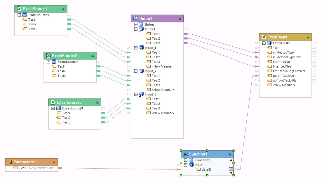
Union transformation is an example of a set transformation that accepts more than one input set. Union is used to combine incoming data from two or more input sets into a single output. Each input node receives data from a different source or set transformation. Note that an input node in a Union transformation cannot receive data from two different set transformations. The figure below shows an example of a flow using Union transformation being fed by 3 set transformations.
Commonly Asked Questions about Cardinality Errors
“While using Route component I received the following error. Why am I getting this error?”
Message: Cardinality of element paths inconsistent with other source paths
If you look at the image below, you have a map going from ExcelSource 1 directly to Database Destination1. You also have a map going from the same source to a Router and then the database destination. This is a no-no.
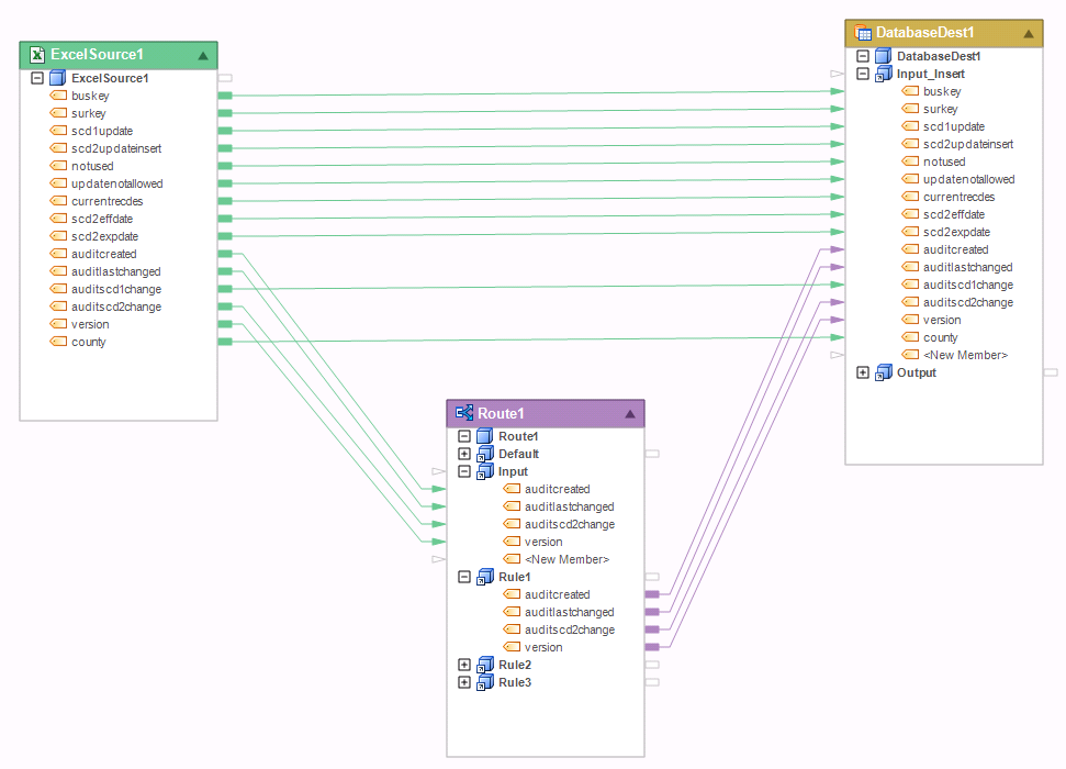
The Route transformation is for routing entire records, not values. You will also run into this error when trying to do this with any set transformation. For example, if you have a Filter transformation instead of a Router there and filtered out all but 1 record out of 10 coming from the Excel workbook. From the point of view of the destination table, how many records should it write? 1 or 10? The counts don’t match up, and this is the reason you get a cardinality error. To avoid this error, a record must flow entirely through the set transformation. You cannot go around it.
Mapping Examples
Below are 15 examples showing the using of correct maps that avoids data cardinality issues, as well as some incorrect uses of maps leading to cardinality issues or other dataflow errors.
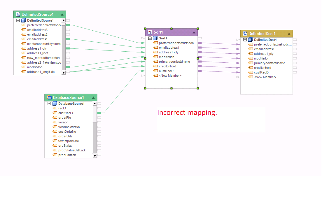
Example 1:
Incorrect input mapping of a Set transformation. The following dataflow has invalid maps into Sort1. Sort1 is a set transformation, and it only allows input maps from one Source/Set transformation. This flow will throw an error at run-time, and will also display a preview error if you try to preview the output of Sort1.
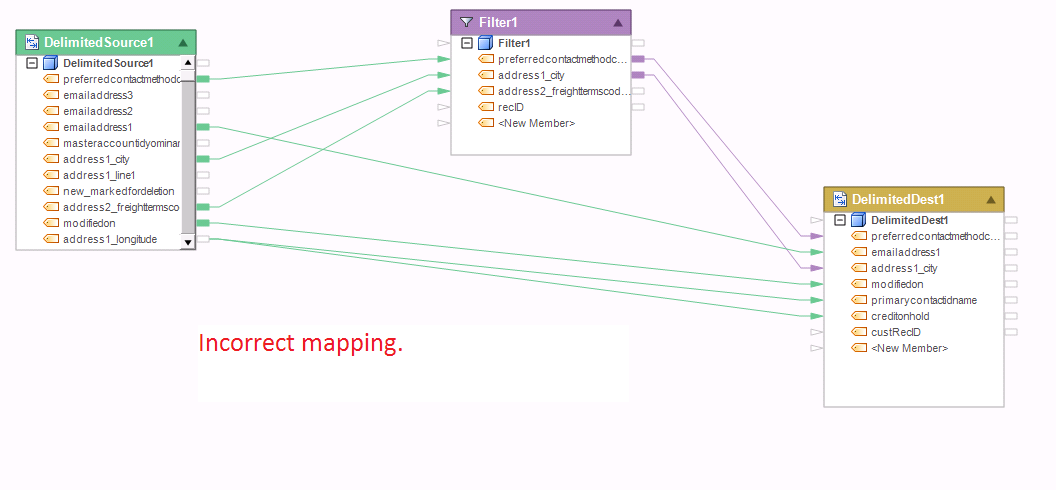
Example 2:
In this example, the destination file is a Set transformation, and as such it does not allow maps from two preceding Set transformations at the same time. In addition, because Filter1 may return a subset of the input set, there is a cardinality issue when mapping that subset together with the full data set from DelimitedSource1.
Example 3:
The following dataflow has correct maps. Each Set transformation in this flow receives input from only one preceding Set transformation. Note that the number of records in DelimitedDest1 may be different from the number of records in DelimitedDest2 because of the different filters applied. There is no cardinality issue here because the flow is writing into two destination files.

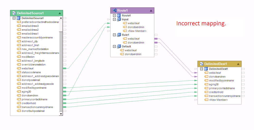
Example 4:
The following dataflow has incorrect maps into the destination file. In this example, the destination Set transformation receives input from two preceding Set transformations, which is not allowed. In addition, only a subset of records will go through the Rule1 path of the router, which would create a cardinality issue when trying to combine that subset with the full dataset out of the delimited source.
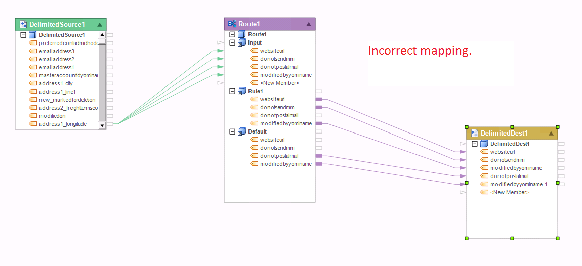
Example 5:
This flow has incorrect mapping feeding into the destination file. The mapping creates cardinality issue with the Router’s output because the different paths out of the Router could each return a different number of records.
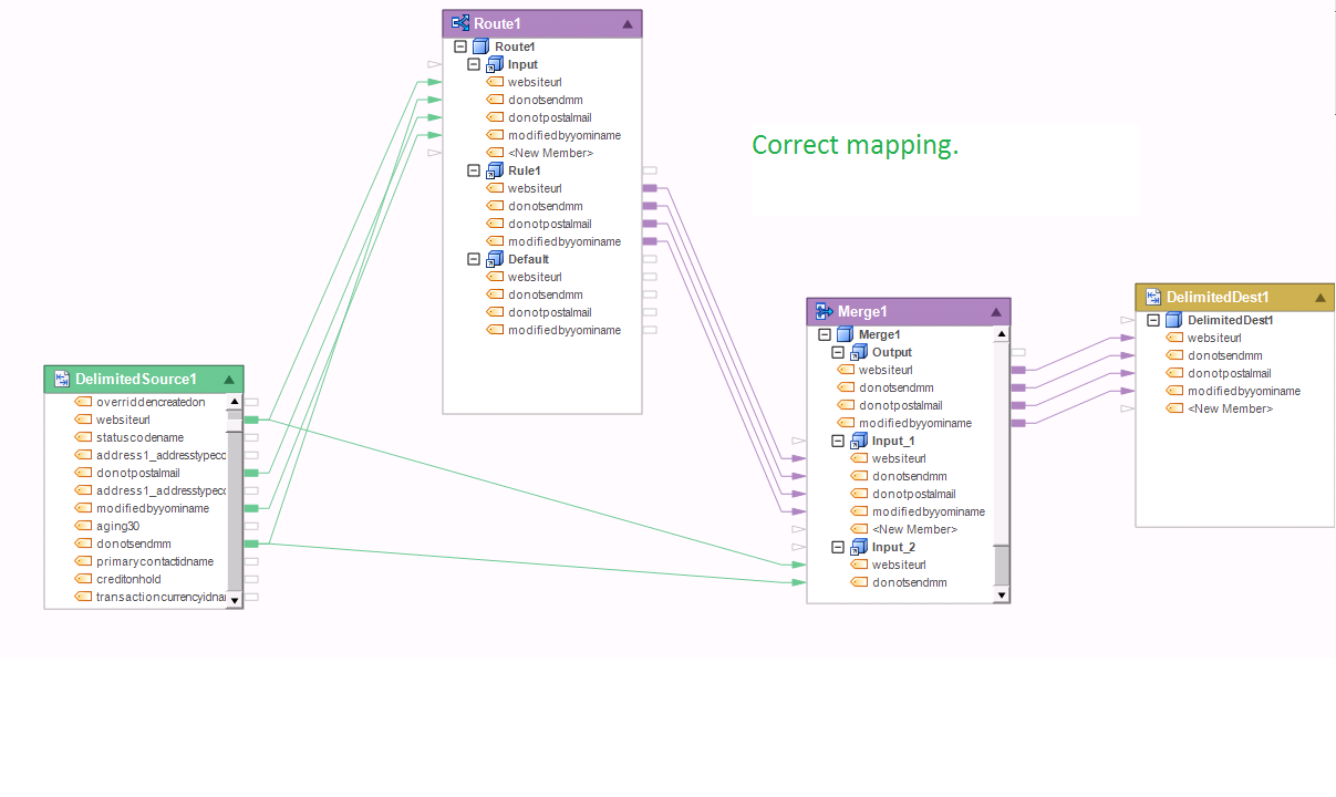
Example 6:
The mapping shown below is correct because Merge transformation accepts input from two preceding Set transformations.
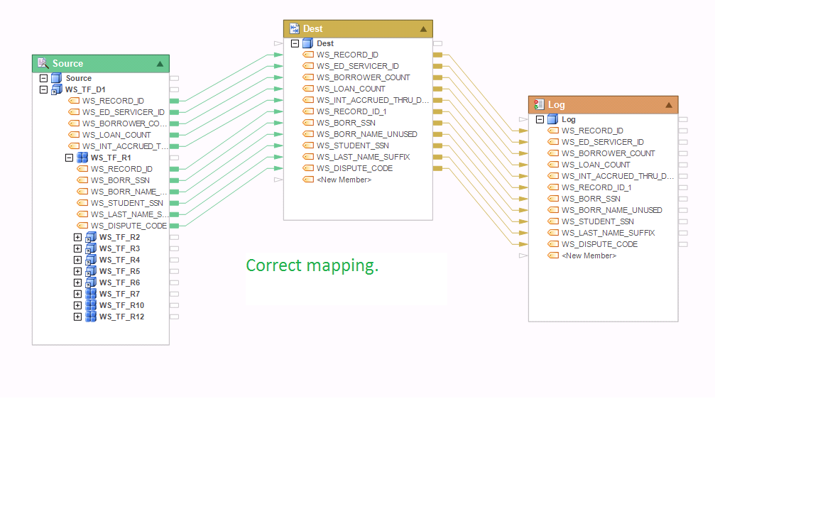
Example 7:
The following mapping is correct. It does not create cardinality issue since it denormalizes the input set by iterating the child collection WS_TF_R1 through each instance of the parent node WS_TF_D1.
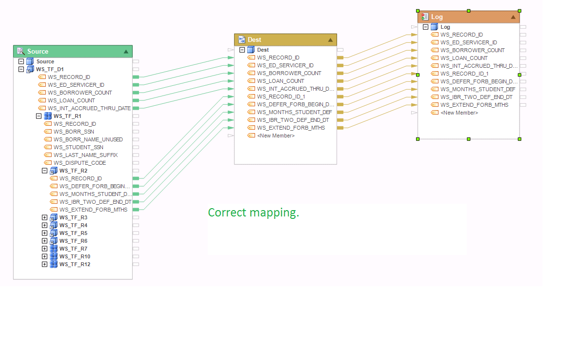
Example 8:
The following mapping is correct. WS_TF_R2 is a grandchild node of WS_TF_D1. It has a 1:1 relationship with its parent node WS_TF_R1, which is a collection child node to its own parent node WS_TF_D1. So in effect, this mapping creates a denormalized record set with each instance of the root node WS_TF_D1 repeated for each occurrence of the grandchild node WS_TF_R2 in the collection.
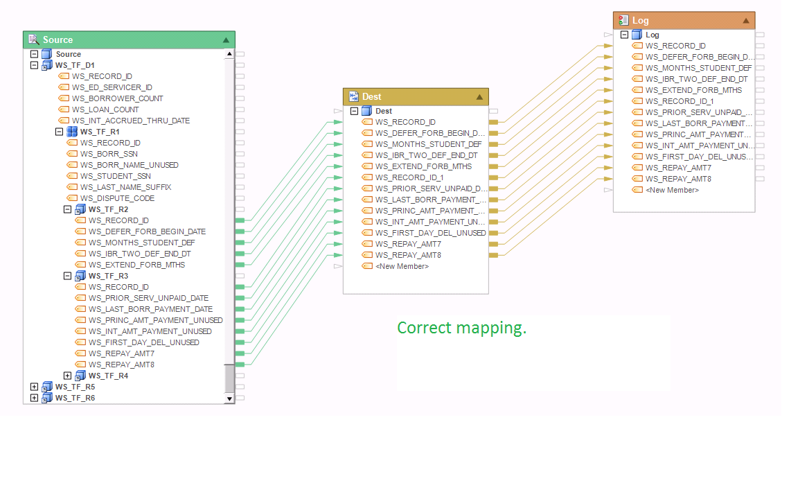
Example 9:
This mapping is correct. There are two sibling children WS_TF_R2 and WS_TF_R3 mapped together. Normally, this could create a cardinality issue, but in this case each of the sibling children has a 1:1 relationship with it parent node WS_TF_R1. As a result, both sibling nodes will return the same number of records, outputting a record for each occurrence of WS_TF_R1 node in the collection.
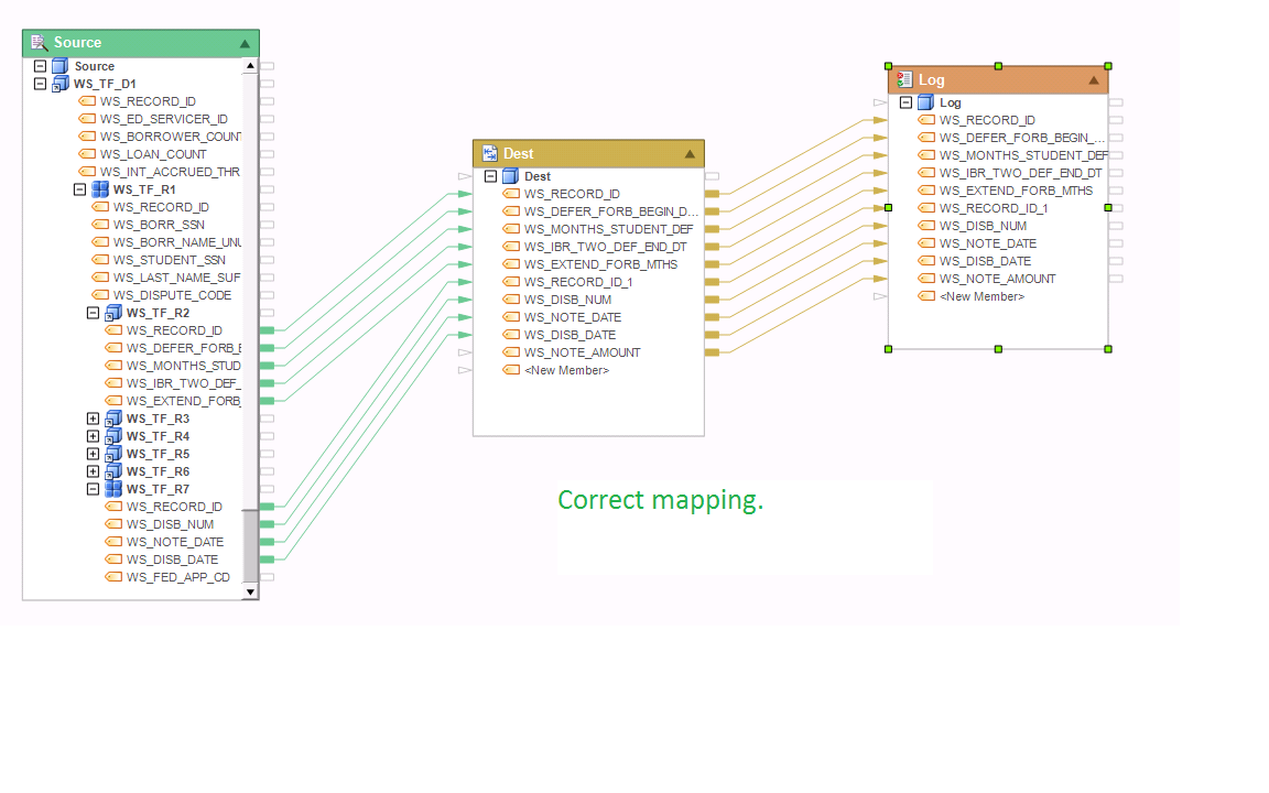
Example 10:
The mapping shown below is correct. In this example, WS_TF_R2 node is a single instance node, creating a 1:1 relationship with its parent node WS_TF_R1. WS_TF_R7 is a collection node to its parent node WS_TF_R1. Both of the mapped nodes, WS_TF_R2 and WS_TF_R7, share the same parent node WS_TF_R1. As a result, there is no cardinality issue here, and this mapping will create a denormalized view of the tree, repeating each instance of WS_TF_R2 for each occurrence of WS_TF_R7 in the collection.
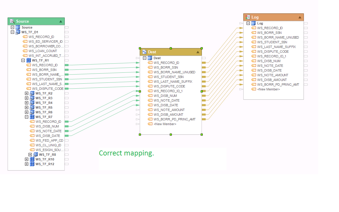
Example 11:
The mapping below is correct. WS_TF_R7 is the child of WS_TF_R1. Both are collection nodes. This mapping will create a denormalized view of the tree, repeating each occurrence of WS_TF_R1 node for each occurrence of its child node WS_TF_R7 in the collection.
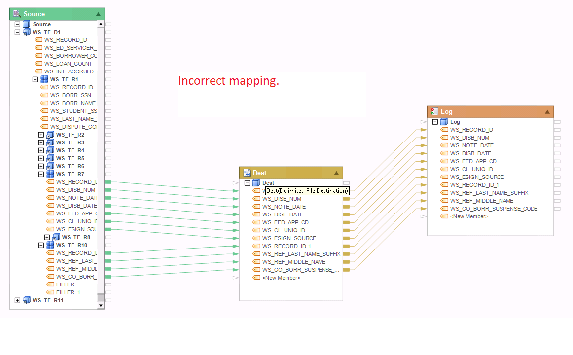
Example 12:
This mapping is incorrect. This flow is trying to map two sibling collections, WS_TF_R7 and WS_TF_10, which are the children of the parent node WS_TF_R1. Because each of the sibling collections can return a different number of records compared to the other collection, this kind of mapping would create an N:M type relationship and so will return a cardinality error.
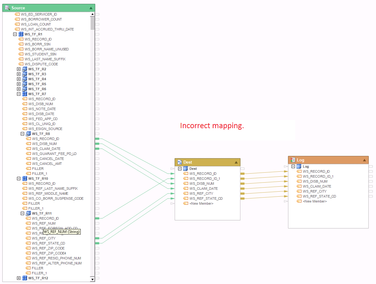
Example 13:
The mapping shown below is incorrect. It will return a cardinality error when the flow runs, or if you preview Dest object’s output. This mapping causes a cardinality issue because it is attempting to combine the output of two single instance nodes WS_TF_R8 and WS_TF_R11 which are the respective children of sibling collections WS_TF_R7 and WS_TF_10. Because each of the sibling collections can return a different number of records compared to the other collection, this mapping would create a N:M type relationship and a cardinality error.
Example 14:
This mapping is correct. It eliminates the N:M cardinality, which would normally be the case when joining two sibling collections, by applying a Flower transformation to one of the collections. The Flower transformation acts as a filter returning the first record from the WS_TF_R7 collection in each instance of WS_TF_D1 node. There is a scope map into the Flower object shown as a blue line connecting the WS_TF_D1 node. This tells the dataflow engine to ‘scope’ the collection at the WS_TF_D1 node level. Because the Flower object returns 1 record from WS_TF_R7 for each record in the root node, this effectively creates a 1:N relationship between WS_TF_R7 and WS_TF_R10.
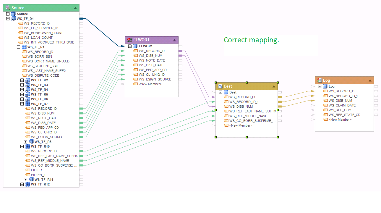
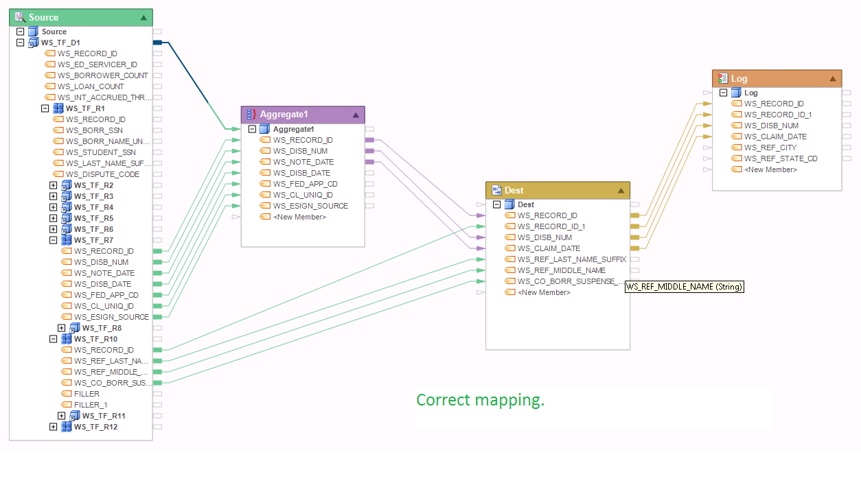
Example 15:
Another example using correct mapping. The mapping here is similar to the one in the previous example, but instead of a Flower transformation, this dataflow uses an Aggregate scoped at the root level. The aggregate returns the max disbursement date among all claims in the WS_TF_D1 record, effectively returning one record from each WS_TF_R7 collection, and as a result, creating a 1:N relationship between WS_TF_R7 and WS_TF_R10. For more details on this type of mapping, please see Example 14.