Linking and Mapping Objects
Mapping Objects in a Dataflow
Most objects on the dataflow have ports. Some have only Input ports, others have Output ports, and still others have both Input and Output ports.
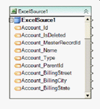
An input port on an object signifies that incoming data can be fed to the object. Because source objects cannot receive data, they do not have Input ports.
Example:
An output port on an object signifies that the object can send data to another object.
Example:
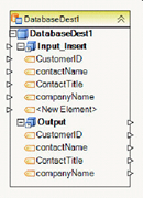
An object having both an Input port and an Output port can receive and send data. An example of such an object is a destination object that is also source to another destination object. Most transformation objects also have both types of ports.
Ports can be of two types: Field ports and Node ports. A field port allows you to map to an individual field. A node port allows you to map to a node including all fields and child nodes in the selected node. The main node located at the very top of the object box is essentially the root node that spans the entire tree (or all fields in the case of a flat layout).
To quickly create field maps between two objects, drag-and-drop a node Output port of the upstream object to the node Input port of a downstream object.
If the downstream object already has fields, the fields with the same name will be mapped between the two objects. If the downstream object has an empty field layout, it will get the same layout as the upstream object, and all the fields will be mapped between the two objects.
NOTE: By default, maps copy value of source into destination and, if needed, convert the value to the data type of the destination element. If you want to copy metadata for the field, you can change the map type to copy field name, field data type, or length to the destination.
To remove all fields from a node, right-click the node and select Remove All Elements from the context menu. This action will also unmap any fields mapped to the fields being removed.
To remove a map between two fields, right-click on the map and select Delete, or left-click on the map and press DEL key on the keyboard.
To remove incoming maps for a node, right-click on the node, and select Remove All Inbound Maps.
Note: For objects with tree layouts in the collapsed state, a single map link will be shown for the entire node, which could make it hard to see how fields are mapped. You can use the Find Map From To capability to automatically expand and position the two trees inside the object box showing how the fields are mapped. To do so, right-click on a map and select Find Map From To.
A similar feature is available when you need to identify which field or fields a given field is mapped to or from. To find the destination field or fields for a given source field, right-click on your field, and select Find Elements Mapped To. To find the source field for a given field, right-click on your field, and select Find Element Mapped From.
Usage
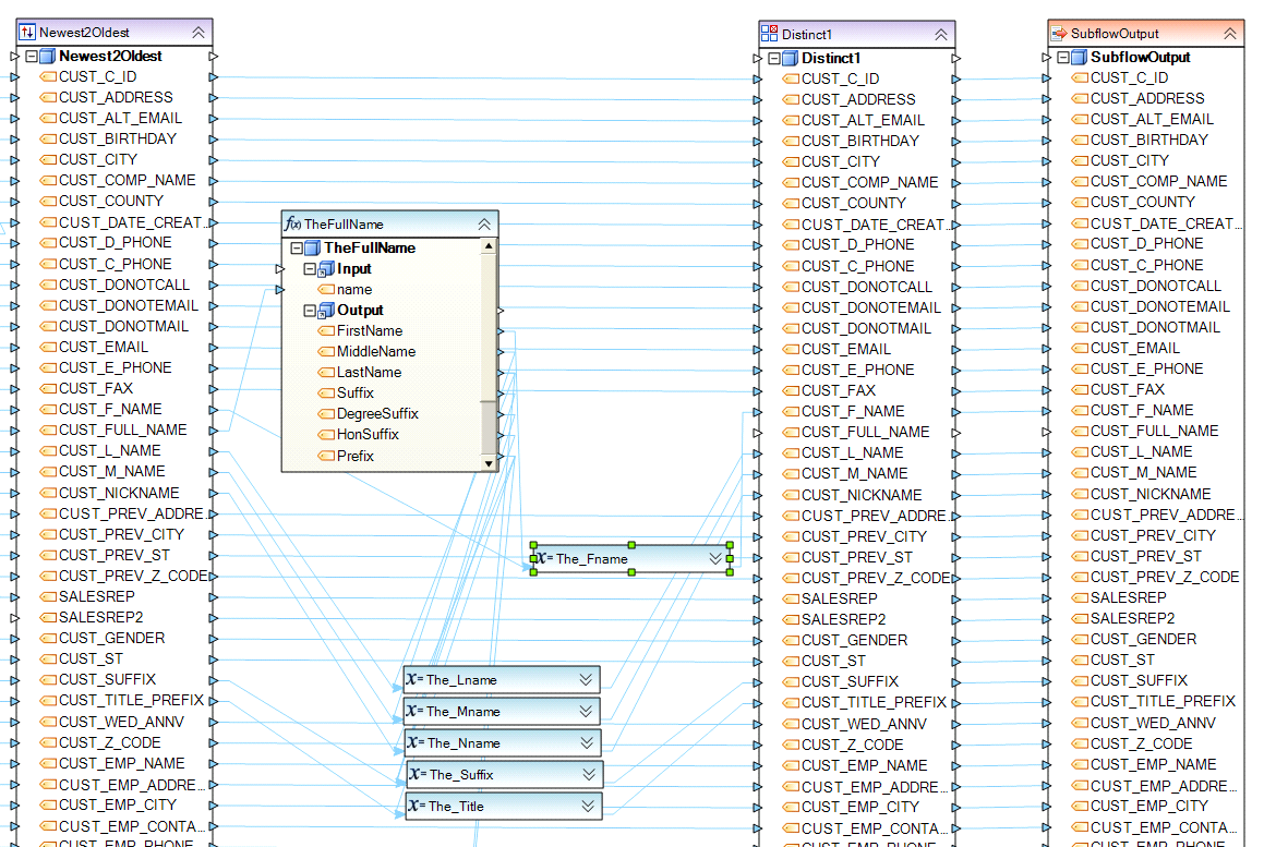
The following segment of a subflow shows objects connected via direct maps. Direct maps make it possible for data to flow from a source field to a downstream field that was mapped to it.
Linking Objects in a Workflow
Ports
Any Workflow Tasks objects you add to the workflow will show Input and Output ports. Ports make it possible to connect an object to another object via links, creating the required workflow path.
The Input port on an object allows you to connect it to an upstream object on the workflow. Conversely, the Output port allows you to connect your object to a downstream object on the workflow. The downstream object representing a task will be processed after the upstream object it is connected to has finished running (with some exceptions, such as the Run Program task, which may not require waiting for the program to exit).
Source objects and Resources objects have no ports and cannot be linked to other objects on the workflow. These types of objects cannot be linked to any specific object as they provide values that can be used by any task throughout the workflow.
All source objects added to the workflow are used in Singleton mode only. A Singleton mode object only returns the first record of data (excluding the header) from the object. This makes it possible for you to get the values from the first record anywhere on the workflow, using the following notation: ObjectName.FieldName.
Similar to Source objects, Resources Objects such as Parameters or Context Info, provide parameters used throughout the workflow. Parameters have a similar notation of ObjectName.ParameterName.
Links
To create links between two objects, drag the Output port of the upstream object and drop it on the Input port of the downstream object.
To remove a link between two objects, right-click on the link and select Delete, or left-click on the link and press DEL key on the keyboard.
Note: By default, the link of Normal type is created between two objects. Normal link means that the downstream object will be processed in the event of a successful completion of the upstream object to which it is connected. Normal links are displayed in green.
In contrast, an Error link can be created between two objects, meaning that the downstream object will be processed only in the event of a failed (error) status of the upstream object to which it is connected. Error links are displayed in orange.
To change the link type, right click on the link and select Change Link Type.
Usage
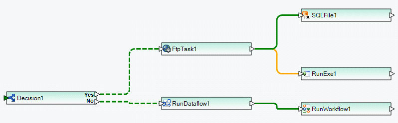
An example of linked workflow tasks is shown below. A green line signifies normal execution flow starting from the object to the left of the line. A yellow line activates execution of the object to the right of the yellow line upon error in the object to the left of the yellow line. A dashed line signifies conditional execution.
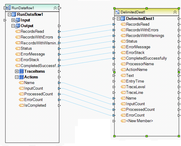
In the following example, a single workflow task RunDataflow1 feeds data to a delimited file. Note that the two workflow objects are not ‘linked’ with a green or yellow line. (A solid/dashed green or yellow line links two workflow tasks to control the flow of execution. For other object types on the workflow, direct field maps can be used to control the flow of data).
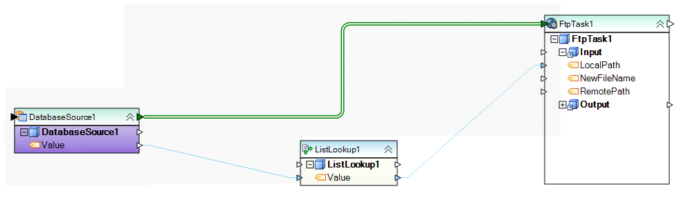
In the following example, a double green line signifies a dependency of a workflow task on the preceding object, DatabaseSource1, which is being used as Iterator.
The following example shows a segment of a workflow with no direct maps between workflow objects (the objects are connected via links, but no field-to-field maps are being used). Dollar sign parameters ($ params) inside workflow tasks are used in this workflow instead of direct maps to reference the appropriate source fields.
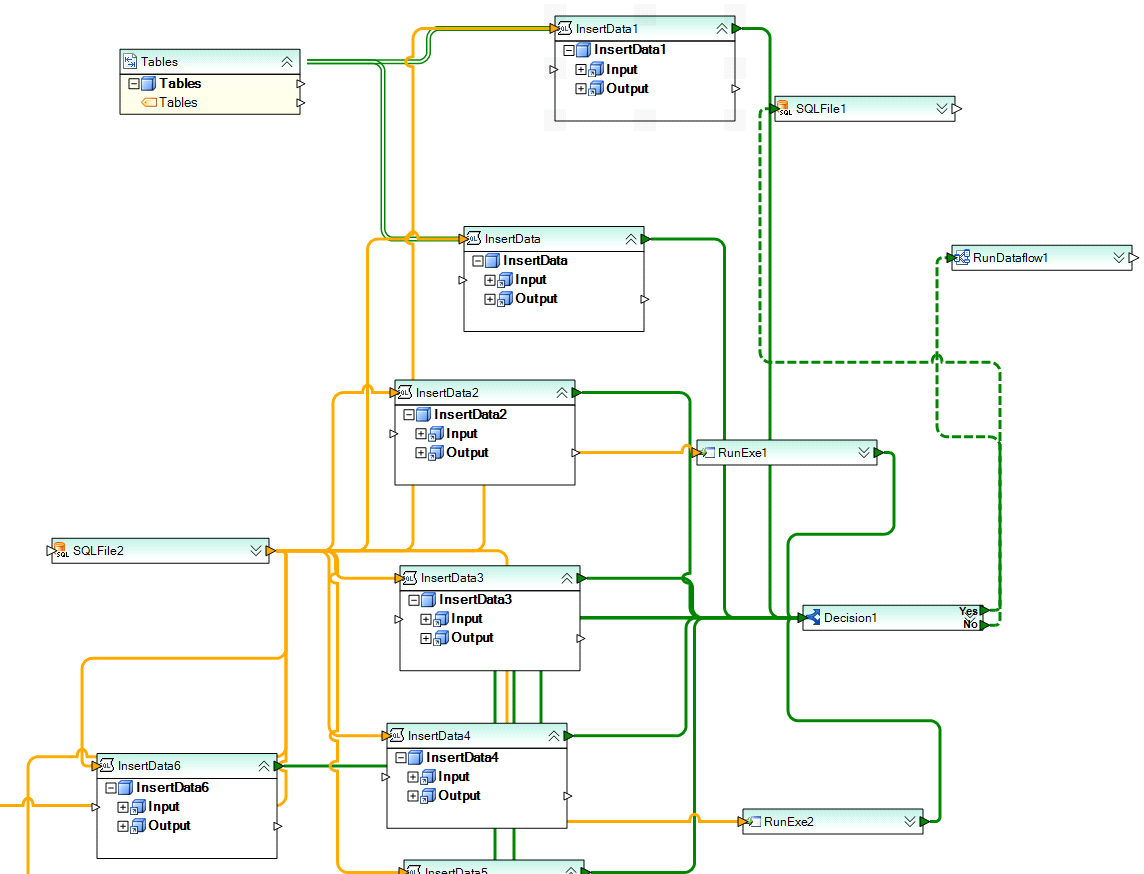
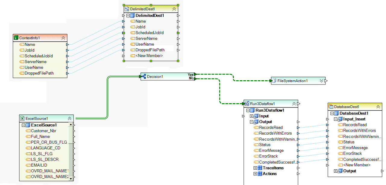
The following workflow includes task links, field maps and source dependencies, as well as two parallel flows, ‘ContextInfo1 -> DelimitedDest1’ and ‘ExcelSource1 -> .. -> FileSystemAction1/DatabaseDest1, in order to create the required logic.