Using ReportMiner to Extract Business Information from Printed Documents
In this tutorial, we will explore Astera’s ReportMiner features.
To mine a report, you need to create a report model containing the definition of the report’s structure, and then use your report source object in a dataflow just as you would with any other hierarchical source object.Let’s demonstrate how this can be accomplished.
We will start by creating a report model.
NOTE: A report model normally has several regions and fields belonging to those regions. An example of a region is the header, footer, Data region, and any additional ‘append’ regions. An example of a field within a region is CompanyName, AccountNo, Quantity etc. A region may have child regions located within that region. A field can only belong to one region at a time, and fields cannot overlap.
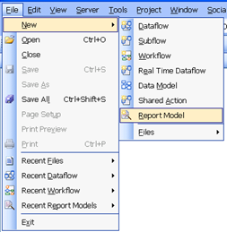
To create a new report layout, go to File -> New and select Report Model.
Select a sample report file in the Open dialog box. We will use this sample report to create our report model. Using a sample of an actual report will allow to ‘visualize’ our report showing regions and fields making up the report as well as their actual values from the sample.
NOTE: Centerprise supports reading flat text reports, PRN reports and PDF reports.
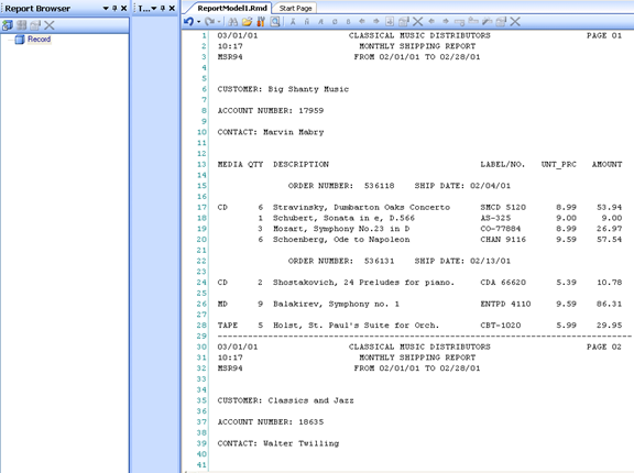
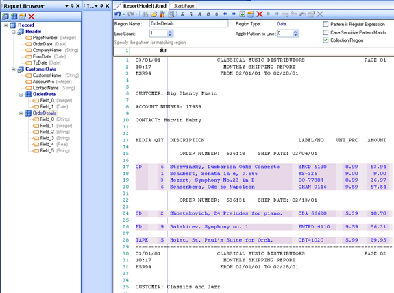
In the screenshot above, we selected a sample report file for Orders. The selected sample is loaded to the Report Definition Editor:
NOTE: You can also load a different sample file in the report definition editor at a later time. Click the  icon on the toolbar and navigate to the file you want to load.
Let’s take a look at this report. At the top of our sample is general Order information, such as Company Name, Order Date and time, Customer Name,Account Number and others. Following it is the detailed Order info, such as order items making up the order.
Our sample report has two logical regions, the Header, the Data region. Unlike some other common reports, this report has no Footer.
The header is at the very top of the report, spanning three lines starting at the line with the order date.

So the first step in creating our report model will be to define the header for our report.
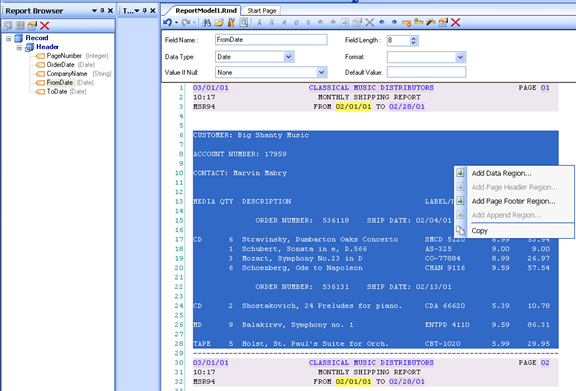
In the Report Definition Editor, select the top three lines. This is the area that covers the Header. Right-click on your selection and using the context menu select one of the following options, shown in the context menu below:
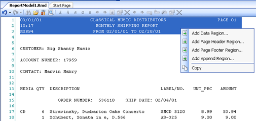
Since we are creating the Header, select Add Page Header Region.
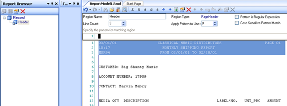
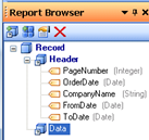
Report Browser on the left hand side of Centerprise now shows a new node Header.
Now, let’s take a closer look at the header. The header in our sample report always starts with a date, shown at the very first line and in the very first character position of the header. We can use the date as an identifying pattern for the header. Any time the  pattern occurs in the report file, Centerprise will treat it as the beginning of the Header.
Let’s enter the  wildcard characters denoting digits as shown below:
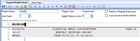
Any time this pattern occurs inside the report, Centerprise will treat it as the starting point of the Header.
Notice that the Report Definition Editor now highlights the header in purple. The header spans 3 lines, as shown by the purple block in the editor. The height of the header or any other region, (i.e. the number of lines that the header spans) is controlled by the Line Count input below the Report toolbar.
The next step is to create fields making up the header.
There are two ways to create fields.
\1. Highlight a field, right-click and select Add Field.
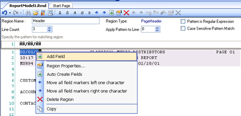
\2. Right-click within the Header area, and select Auto Create fields.
Centerprise will scan our sample report and identify any changing values within any occurences of the Header. These changing values will be marked as fields.
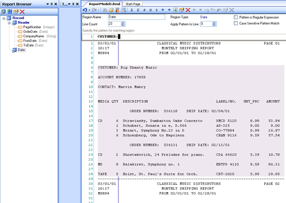
In our example, the Auto Create Fields feature added five fields. They are now displayed in the Report Browser under the Header node. Notice that our new fields are also highlighted in darker purple in the Report Definition Editor.
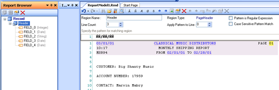
The fields created this way are assigned unique names, such as FIELD_0, FIELD_1 and so on.
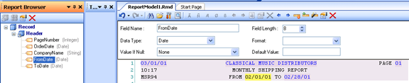
You can rename a field if needed. Let’s rename our newly created fields to make them more descriptive.
\1. select a field in the Report Browser, double click and enter the new name
Or:
\2. select a field in the Report Browser, right-click it and select “Rename”
Or:
\3. select a field in Report Definition Editor (the selected field is highlighted in yellow), right-click and select Rename from the context menu.
NOTE: The selected field is always highlighted in yellow in the report definition editor.
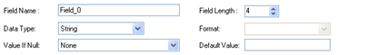
We can also change the field’s data type if needed. In our example, Centerprise was able to correctly assign fields data types from our sample report:
Now that we created the definition of the Header, let’s look into the main region of the report. As we saw earlier, the main region starts with the Customer Name and then includes Account Number, Contact Name, and finally specific order details.
Let’s select the main region in the report definition editor, then right-click it and select “Add Data Region” from the context menu.
This will add a new node “Data” in the Report Browser. This new node has no fields at this point.
Notice that Centerprise assigned the default vertical size of this region as 23 lines based on our selection. We can adjust this number as needed by using the Line Count input under the toolbar.
Now we will identify the starting point of the region. Place the cursor at the position where the text ‘CUSTOMER:’ begins as shown in the screenshot, and enter CUSTOMER: in the pattern text input.
Report Definition Editor highlights any occurrences of the Data region in report. Remember that we can easily adjust the height of the region by using the Line Count input.
Let’s now rename our region CustomerData. Now our report has two regions: Header, and CustomerData.
Now, let’s identify the fields making up CustomerData region.
You can either manually assign fields, or you can use the Auto Create Fields feature.
To manually add a field, highlight a field with the mouse cursor, right-click it and select Add Field. A new field is added to the Report Browser. The Report Definition Editor shows all the occurrences of this field in the report.
NOTE: To automatically add fields, right-click within the header area, and select Auto Create fields. You can then modify, rename, add or delete fields as necessary.
Next, let’s take a closer look at CustomerData. Notice that each Customer can have one or more orders, and each order may have several items in it. In Centerprise terms, we say that the region has a collection of items, or to put it simply, is a Collection. Also note that order data in located within the CustomerData region we defined above. In other words, CustomerData region is also a container for order details.
Select CustomerData node in ReportBrowser. Right-click it and select Add Collection Data Region. This will add a new region under the CustomerData node. The default name here is Data, which we will rename OrderData to make it more descriptive.
Now, let’s now define the starting point of our new region.
Type ORDER NUMBER: in the text pattern input.
The report definition editor highlights all instances of OrderData region.
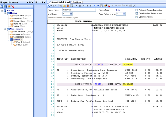
Right-click anywhere within our region, and select Auto Create Fields. This creates Order Number field and Ship Date field, named Field_0 and Field_1 respectively. Let’s give these fields more user-friendly names.
As we saw earlier, a Customer can have more than one order (which in Centerprise parlance is called a Collection of items). Whenever a node has a collection of items, we need to turn on its “Is Collection” property as shown below. Notice that the appearance of the icon for ORDER node in the report browser changes to help identify this node as collection. Note that when we add a Collection Data Region via the context menu, the “Is Collection” property is enabled automatically.
Now, let’s create the definition of Order Items. Select CustomerData node in the Report Browser. Add a new Collection Data Region in the report definition editor in the same manner we did earlier.
Specify the text pattern that will identify our order items. In our example, we will use part of the Quantity data followed by a space character to identify a line with the order item. To that end, enter “Match any digit” and then “Match any blank character”  as shown below.
Next we will rename our new region OrderDetails, and auto create fields using the protocol we demonstrated earlier.
This action adds 6 fields, such as media type, quantity, description, label/no, unit price and amount. The fields are named by default Field_0, Field_1, so we will need to rename them as desired.
Our sample report does not have the footer. If necessary, a footer can be added in the same way we added the Header and Data regions above.
We have now created the report definition.
NOTE: Report definitions are used by Centerprise to correctly parse, interpret and assign data as it is fed from the report source. Report definitions are assigned *.rmd extension.
Let’s save our report model, by clicking Save icon on the main toolbar. Now we can preview our data to see how it is parsed by Centerprise.
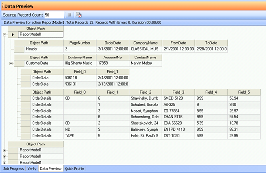
Click the  icon on the top toolbar. This opens the Data Preview window showing the entire report structure with the actual values for all the fields we have defined above.
Let’s now take a look at some additional functionality that Centerprise offers to help you customize your report.
Selecting Fields and Regions
To select a field, left-click on it in the Report Browser’s tree. The field is highlighted in yellow in the Report Definition Editor. Some of the more common field properties are displayed in the top pane of the editor:
To select a region, click on it in the Report Browser’s tree. The region is highlighted in light purple in the Report Definition Editor, and the fields in the selected region are also highlighted in darker purple. The top pane shows the properties that are applicable for the region.
Managing Field and Region Properties
To view and update all other properties of a field or a region, right-click on a field (or region) inside Report Browser, and select Edit Field (or Edit Region) from the context menu.
The same functionality is also available on the top toolbar, by pressing the  icon.
icon.
You can also access field properties by right-clicking the field in the Report Definition Editor and selecting ‘Field Properties…‘ from the context menu.
Renaming Fields and Regions
To rename a field, double click it on the tree in the Report Browser and enter a new name.
To rename a region, double click it on the tree in the Report Browser and enter a new name.
You can also rename a field or a region by entering the new name in the Name input on the top pane.
Deleting Fields and Regions
To delete a field, right-click it in Report Browser or Report Definition Editor and select Delete Field.
To delete a region, right-click on a region (or a field inside the region), and select Delete Region from the context menu. Note that this action will also delete any fields in that region.
Customizing Fields
After your field has been created, you can change its start position by moving it a number of characters to the left or to the right. Right-click on a field and select “Move Field Marker Right One Character” or “Move Field Marker Left One Character” from the context menu. Repeat as needed to move the field the desired number of characters. Note that the same functionality is also accessible from the top toolbar via the  icons accordingly.
You can also change the field length, by selecting “Decrease Field Length by one character” and “Increase Field Length by one character” from the context menu. Repeat as many times as needed to change the field length by the desired number of characters.
Note that the same functionality is also accessible from the top toolbar via the  icons accordingly.
To auto determine field length based on the available sample data, right-click a field and select “Auto determine field length“ from the context menu. Or click the  icon on the top toolbar.
Alternatively, you can also move all fields within the same region left or right by a specified number of characters. To do it, right-click on a region or field, and select “Move All field markers left one character” or “move all field markers right one character”. You can also use the  icons on the top toolbar.
NOTE: To undo any action in the editor, use the Undo dropdown menu on the toolbar or press CTRL + Z.
Identifying Text Patterns for Fields and Regions
The following options are available to help you create a text pattern that will identify the starting point of a field, or a region.
 Match any alphabet
 Match any digit
 Match any alphabet or digit
 Match any non-blank character
 Match any blank character
For example, to match a date 12/15/2011, you can use the pattern  is “match any digit”.
Report Options
To change report options, click  icon on the report toolbar.
The following options are available:
Sample File Path – provides the path to the sample report file that you want to use for creating your report model.
Line Count – controls how many lines are loaded from the sample file
Other useful options are Tab Size (default value of 8), Font and Numeric Format.
Let’s now preview our sample report based on the report model we have created. To preview it, click  icon on the Report toolbar. Our report displays in the Data Preview pane as shown in the screenshot below.
Now that we created and previewed our report, let’s add it to a dataflow so we can read the entire source report and feed it to a destination object.
Go to File -> New -> Dataflow. This creates a new dataflow.
Using the Toolbox pane, expand the Sources category and select Report Source.
Drag and drop Report Source onto the Designer.
Double click ReportModel1 object that we just added (or right-click it and select Properties) to open the Properties dialog.
Using the properties dialog, enter the path to the report source file and the report model. The report model location should point to the report model we created and saved earlier.
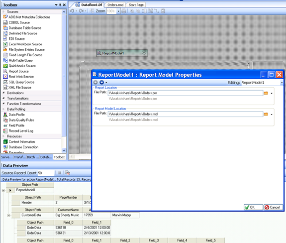
Click OK to close the dialog. ReportModel1 object shows the report structure according to the report model we created:
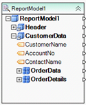
NOTE: You may need to expand the tree nodes to see all the child nodes under the root node.
Our new report source is ready to feed data to the downstream objects in our dataflow.